

FRANKEN-TROL
The Franken-trol is the result a brainchild of mine and several month’s worth of gathering parts in order to build a fairly powerful haunt controller that could handle a complex scene or room. Some of the parts were purchased and some were acquired via grave robbing (dumpster diving). Since I used some salvaged parts, I can’t conclusively determine how much the total cost is thusfar, but if you are interested, a little research on the WWW should give you a rough estimate. I acquired the parts over a long period of time so, the total cost was not real high on my list of priorities (within reason). While I can’t say that the project has been dirt-cheap, so far it hasn’t required me to get a second mortgage on the house either.
The intended use of this controller is in a pro-haunt event and is probably not practical for any but the more seriously afflicted home haunter. This is by no means a top-of-the-line controller, but rather, a combination of smaller, “lesser-powered” (and less expensive) controllers of different breeds. This project takes 4 controllers from different manufacturers and puts them to work with each other to form a completely self-sustained control unit, all that is further required is to connect some loads (lights, etc.) to it’s outputs, and programming. It is conceivable that the components can be acquired separately and used as-is with the understanding that they could be assembled into “something else” at a future date. Essentially, this is an example of “something else.”
To describe all of the functions that are possible to be achieved with this controller would be next-to-impossible, and could only be described as:
It can do everything an industrial PLC can do, everything a BooBox can do, everything an APC16 can do, and every combination of using them together; which is exactly what it is and what it does.
 +
+ +
+
 +
+
![]() +
+
 =
=
FRANKEN-TROL
To help you visualize what some of the concept is behind this controller, think of it this way:
You have a console with switches on it. This console can be located in a central, convenient and/or concealed location, remote from the actual device that you wish to control. Connected to the console, only by small low-voltage cables, are boxes in which you plug in your controlled device(s). These boxes are close to the devices, which eliminates the need to run long, large power cords all the way back to the console. Inside the boxes are relays, which are in essence, an electrically controlled switch. This allows you to remotely control the loads, using low-voltage to do the switching. When you press the switch at the console, you are switching the low-voltage on and off, which is actually switching the remote relay on and off, which in turn is switching the end load on and off (light a spotlight for example).
Now, visualize playing an audio file and during it’s play, you manually press switches with your fingers to turn things on and off at strategic times, in synchronization with the sound. Additionally, in order to set up for an enhanced visual experience, let’s say you want to add things like a fogger and/or some other kind of effect. This could be done using a cycling timer remote (which IMHO, have a habbit of knowing the worst times to be on or off) or, manually actuated by you at the time that you really think it should be.
So, what we have is YOU pushing buttons to make things happen at the times that you want them to … manual control. Now, what if you could RECORD the movements of your fingers pushing buttons, save this information and then play it back when you want it to? The result is automated control, synchronized with the audio!
It is this very concept of recording switching actions in real-time that unleashes the power of the APC16, the BooBox and other similar-concept controllers by various manufacturers. Now, add to that, the ability to base certain events (output controls) on certain conditions (e.g. inputs based on position, proximity, elapsed time, etc.) that are common in industrial applications … and you end up with a Franken-trol!
There were several criteria that were considered in the component selection and construction of this controller, among them were:
|
Ability to control synchronized audio and visual aspects of the “show” | |
|
Assemble from “off the shelf” items | |
|
Real-time programmability (no scripting in code) | |
|
DCS (Distributed Control System) – well, sort of | |
|
Stand-alone Operation – no PC required, except during programming | |
|
Future expandability | |
|
Variable load handling capability (system ampacity) | |
|
Ability to connect a variety of input/trigger devices | |
|
Ability to connect a variety of output (loads) |
Each of these criteria will be discussed in the following commentary. Along the way, I may add product review opinions, so take that for what it’s worth.
GATHERING PARTS
The first component to make it into the pile of body parts to be assembled was the BooBox. I had always been intrigued by this device since I stumbled on it at Transworld ’04, and then at Transworld ’05 I couldn’t put it off any longer and ordered one. This little box, although it may seem slightly pricey, is worth every penny after you get over some minor sticker shock. UPDATE: Check out the new lower price!!! The BooBox is intended to be a stand-alone controller for a haunt room. As previously described, it has the ability to play a sound file (e.g. MP3) through it’s on-board audio amplifier and simultaneously activate output devices in synchronization with the audio. One of the most important features of it is the ability to program the output devices in real-time. In other words, you play the audio file and press buttons on the RTP (Real Time Programmer) at the times you want some kind of output, and it records your button-pushing actions. When you play it back, the outputs are on at the times that you had the button(s) pressed and off at the times you didn’t have the button(s) pressed. It will then store these data files as a show on a removable flash card. Without getting too detailed or sounding like a sales pitch, the BooBox and it’s ability to establish a timeline for which other events or actions can be based, is essentially the heart and mouth of this beast.
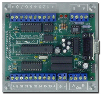
The next crucial component to be collected was the APC16 from Hauntbots. Pete Rondeau was showing this amazing little device at Ironstock ’05 and immediately caught my attention. The APC16 was created as a controller for animatronic haunt props, and has 16 output channels that can be set up to actuate devices such as solenoid valves or relays. I can’t say enough good things about this controller and besides, Pete is one heck of a nice guy! At $150, this thing is a bargain, and is amazingly powerful, versatile, and with it’s CAD/CAM aluminum chassis mounting base, is practically a work of visual art. Again, one of the most important features (for me) is the real-time programmability. Programming is done via a PC using the Hauntbot software, very similarly to the method described above, except you use your PC’s keyboard keys or a joystick instead of a separate programming ”console.” The recorded show file is then downloaded to the controller, from there, it runs stand-alone upon receiving a trigger signal. Although I didn’t realize it at the time, another handy feature of the APC16 are two outputs (relay contact closures) one of which actuates upon the START of a show and the other on the END of a show … more on the use of these later. The APC16 and it’s ability to control other devices, makes this little powerhouse the brain of the beast. In one form or another, practically every other device in the Franken-trol either talks to, is talked to, or controlled by, the APC16.
A special note of THANKS goes to Pete, from HauntBots!
Without his help on this project, it would have never come to life. I know for a fact, that there are tentative plans to make this very cool little controller even better, and my advice to anyone even considering assembling a controller to do whatever, is to hook up with Pete!
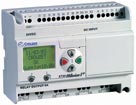
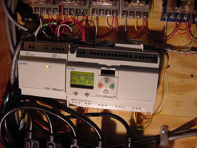
Next, we exit from the haunt-genre controllers and enter into the industrial control world. The Millenium II (M2) from Crouzet is a cool little Programmable Logic Controller (PLC) that is reasonably priced and has an important feature (again, for me) of being able to be programmed using logic layout (AND, OR, NAND, NOR etc.) versus the cumbersome ladder logic that is found in most industrial PLC’s. The model that I am using is the XT20, 24 VDC with 12 digital inputs and 8 analog inputs with 8 relay outputs. Although in Franken-trol’s debut configuration, the M2 is not really doing too much heavy-duty controlling, what it is doing is very crucial. More is planned for using this controller in other functions as this project evolves. As it stands, the M2 can be considered the ears of the beast, as well as a couple of other vital organs :-)
![]()
http://www.chauvetlighting.com/system/fixtures/sf8005.html
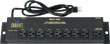
Aside from some miscellaneous electrical components (relays and bases, wire, boxes, receptacles, etc.) the remaining parts are from the stage lighting genre … well, actually from the mobile DJ lighting genre. They are 3 Chauvet SF-8 remotely-controlled relay power distribution packs. These are a simple package that consists of a rack-mounted, 8 channel, manually switched control unit that operates 8 relays individually in a remote (wired, via a 9-conductor cable) relay pack. These relay packs can be daisy-chained via an input and output connector to distribute the controlled power to multiple locations (more on that later). Please note that there are no automated or “intelligent” capabilities to these control systems. They are merely a set of relays that turn on and off when you press a button on the control unit. The SF-8 systems are the arms and legs of the beast.
NOTE - This prototype Franken-trol uses model SF-8 units from Chauvet. During a little research in preparing this tutorial, I see that the SF-8 has been replaced by a SF-8005. It looks to be very similar, with a couple of "improvements?!?" I haven't tried any of these new ones, but my guess is that the procedure on the new ones would be the same. There are also similar units by other manufacturers that may prove satisfactory.
ASSEMBLY (STITCHING HIM ALL TOGETHER)
Originally, the plan was to assemble this thing in early fall of this year, for use at Halloween in a fairly complex outdoor display as a test-run. I had the scene pretty well planned out, had most of the props, to at least see how well it would work and even had a soundtrack developed. Problem was, the controller wasn’t built yet. Then the dreaded day-job demands ended up taking all my time and I wasn’t able to have it up-and-running in time for it’s planned debut. Halloween came and went and all-in-all it turned out OK, but nonetheless it was sans Franken-trol. THEN, on the weekend before Thanksgiving, the video of Carson’s house with the Wizards In Winter synchronized light/sound presentation hit the Halloween lists. Admittedly, this struck a chord deep inside me and the flurry of chatter about how this could be done prompted me (along with some tender loving nudges [read: with a cattle prod] from my wife Kity) to assemble the parts into this, the prototype version. So, the last 4 week’s (~Nov. 20 to Dec. 18) spare time has gone something like this; decorate outside of our house ‘til fingers get numb (it’s friggin’ cold and snowy here in Michigan) work on controller ‘til thawed out, decorate outside of house ‘til numb, work on controller ‘til thawed … and so on.
Ironically, the only enclosure that I had on hand is a crude but stout wooden box that housed the very first haunt controller that my father and I built from scratch, circa 1983. This high-tech wonder incorporated a motorized cam “sequencer” made from a Volkswagen Beetle windshield wiper motor and a B&D can opener gear assembly, turning a piece of threaded rod with an arrangement of cam lobes cut from plexiglass that actuated a switch control arm …enough on that marvel of engineering and construction.
What better candidate (and still stay within the Frankenstein theme) for a controller enclosure than a resurrected controller box? So, I gutted it out and amazingly re-used a few of the parts such as relay bases and outlet boxes, and then re-assembled it using new innards.
Mounting of the various components was done pretty much done on the fly, as space in the box permitted and could have been done in a number of different ways. I installed power cord assemblies on devices that didn’t have one, and plug everything into internally-mounted 120VAC receptacles. This provides a safe and reliable method of connection and disconnection. Just because you always need some, I also installed a couple of spare receptacles that come in handy during programming, etc. The BooBox is mounted un-modified in any way, with the two 120VAC output channels switching 120VAC coil relays. This way, the only significant loads that the BooBox sees are the two on-board dimmable channels. All other channels of the BooBox simply operate a relay.
THE HACKING
Since none of this stuff was ever intended to be used with any other of this stuff, naturally, some hacking is necessary. Fortunately however, it is limited to the SF-8 control box units. Although the hacking is low-tech, it does involve some soldering and running multi-conductor cables from inside the SF-8 box to be connected to the APC16 the BooBox, relay terminals and the M2 outputs. Essentially what I did was solder a pair of wires across each side of the momentary-contact “bump” buttons of the SF-8. Electrically, the outputs of the APC16, BooBox and M2 provide continuity across these wires instead of the bump button (in parallel with the button). Other than that, the SF-8 units function in the same way they normally would. Virtually all of the output wiring, with the exception of the BooBox dimmable channels, is connected to the bump buttons in one of the SF-8 control boxes. This is literally, the connection point at which the system meets manual control with automated control.
PHOTOS
Here is a photo of the M2. As you can see, there are plenty of Inputs and Outputs to play with in future configurations of the controller.
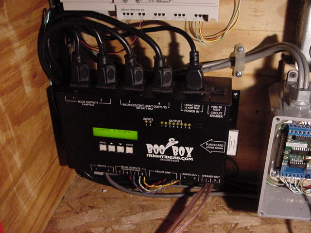
Here is the BooBox. You can see the M2 just above it and the APC16 to the right (cover removed). The cords in the top of the BooBox for channels 1&2 are just connected to 120VAC relay coils. Channels 3&4 are connected to duplex receptacles on the side of the box, these are the 2 dimmable channels and cannot be run through the relay setup, so you do have to run 2 extension cords to the controller if you want to use these 2 channels. The BooBox allows you to configure these 2 outputs as on/off if you wish, but I like the dimmable function, so I ran the 2 extension cords. Wiring at the bottom is speaker outputs and the 4 relay output channels that are also run through the relay controllers.
The APC16. Everything in the Franken-trol is somehow connected to it.

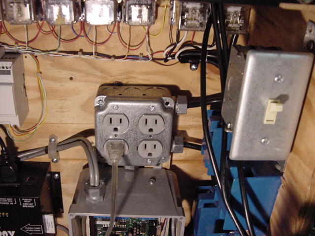
Grand Master switch on the right. Below that (blue boxes) are receptacles for the dimmable BooBox channels. Center is just a pair of duplex receptacles for convenience power (programming, etc.) one receptacle is switched, one is hot whenever the unit is plugged in.
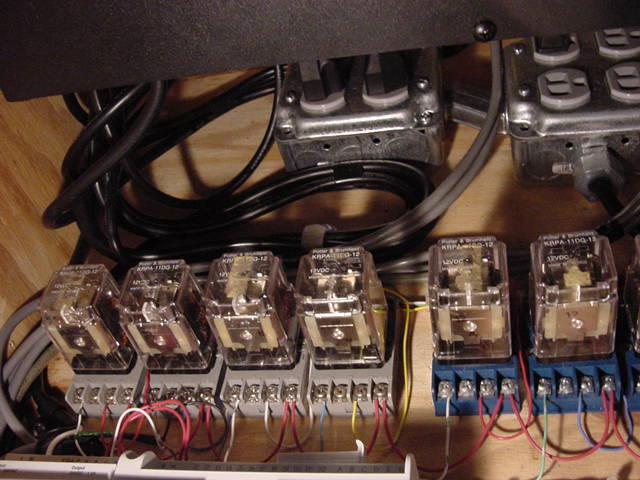
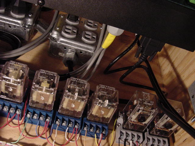
This is a view up and behind the SF-8 controllers (you can see the bottom of one at the top of the photo). These are switched receptacles that are controlled by the Grand Master switch. All of the internal control devices connect to these receptacles. There are a couple of spares for future goodies :-) The relays are driven by the APC16 and interface to the SF-8 controller.
Again, looking up and behind the SF-8 controllers. The D-Sub 9 pin (serial-type) cables on the right are the only connection to the Franken-trol, with the exception of the two extension cords mentioned earlier. These three 9-conductor cables control 24 channels (8 X 3). The connector with the yellow heat-shrinked tubing on it is the multi-conductor cable that is hacked across the bump buttons on the SF-8.
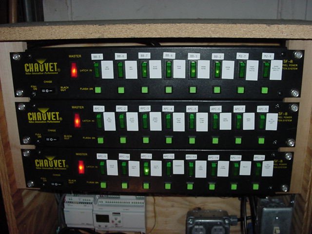
These are the 3 SF-8 relay pack controllers. Each channel has a lighted on/off switch, which comes in handy for use in setting up (and focusing if applicable) of the loads. You can "bump" or "flash on" using the momentary contact switches or you can "latch it in" and leave on using the maintained switches. It's pretty cool to watch your programmed show on all of the lighted switches when it plays back ;-)
DESCRIPTION OF OPERATION
Here is a link to a simplified one-line block diagram that shows the control signals that are used between the various devices:
images/DeeEyeWhy/Franken-trol/Franken-trol_Diag.pdf
If you have made it this far, and are still interested in how this works, I suggest printing the above diagram to follow along with the description.
When power is applied, the BooBox defaults to operating in it’s Ambient Mode. So, depending on whether or not you want to use this ambient scene, determines what you program into it. If you do not want to have any audio and/or outputs on upon power-up, you simply play an “empty” scene with no audio and/or no outputs on. If you want to have just an audio soundtrack, you can do that. Or, if you want just output(s) on, for lights as an example, you can do that also. When the Franken-trol is first turned on, it is essentially just using the BooBox in this Ambient Mode. An audio track loops endlessly, and the Franken-trol’s outputs 1 – 6 plus the 2 dimmable channels are available to be programmed and played as desired. The only difference between the “standard” BooBox hookup/load connections is that the D.O. (Digital Outputs) are being run and distributed through one SF-8.
Starting of a show is determined by the M2 and can be based on any of it's inputs or internal programs (timer, etc.) In this, the first version of hookup, the show is started by pressing an on-board button on the M2. An output on the M2 sends the START SHOW signal to the APC16 (green line on the above diagram). An APC16 relay contact output (dark blue line) tells the BooBox to start (Input 1). The APC16, BooBox and M2 all "play show" simultaneously for the duration of the show. The possible duration of the show is determined by the APC-16 capacity (~12 min. @ 30 frames/sec., longer @ slower rates) and by the removable Flash Card media of the BooBox. In it's "test-drive," I recorded 2 TSO songs for a show length of 8 minutes, which is a pretty long show when you think about it, and had no problems at all.
When the show is finished playing, the APC16 relay output (magenta line on the diagram) tells the M2 that the show has ended, the BooBox returns to it's Ambient Mode, a timer circuit in the M2 starts and allows it to play in this mode for <adjustable> time, and then the whole cycle starts over again and will endlessly loop without any other "operator" actions.
During the show, the outputs of the APC16, BooBox and M2 (light blue lines on the diagram) operate the relays in the relay packs through the SF-8 controllers (red lines on the diagram). Black lines are connected to actual loads.
IT'S ALIVE !! (PROGRAMMING)
If there is a disadvantage of this beast vs. other controllers, perhaps it would be the necessity of using 3 different programming methods and software. Although the BooBox can be programmed with the RTP, if there are any tweaks that are to be made, you will most-likely find yourself using the time-line-based Scene Editor software. And similarly, you must also use the Hauntbots Programming Console software. Last but not least, is the M2 programming software.
I believe that all of the software for the various devices that were used in this project is downloadable free, at the websites of the manufacturers referenced throughout.
With a little experimentation, I was able to program the beast without becoming totally frustrated. In the video at this link;
the programming is essentially "raw," in as much
as it is an un-edited recording of me pushing buttons. Very little time
was spent in either of the editing programs.
FUTURE PLANS
Future plans for the Franken-trol include of course; MORE CHANNELS! As it is presently configured, the Franken-trol has 32 available channels 26 of them being used for output devices (refer to your diagram again). For the next project, I would like to just use an APC16 and a couple of the relay pack controllers, and link it up with the Franken-trol, to get a 16 channel slave unit. For now, I am going to play around with the 26 channels and see what I can do with them.
Also, I have an idea for a "cheater" that hopefully will aid in the initial programming/synchronizing of the BooBox and APC16 that I am going to tinker with.
Hope you enjoyed this tutorial-of-sorts. If you have any questions or comments on how to make it better, you can e-mail me at: thirstinhowl_iv@defrightful dot com
-Thirsty-